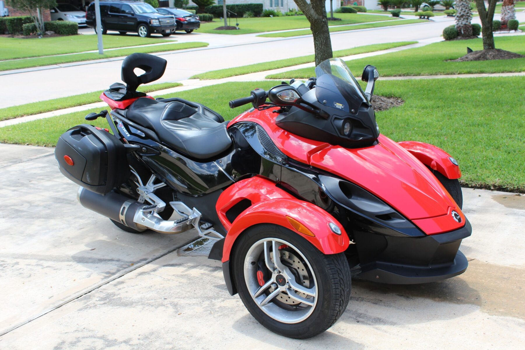
 I bought a used 2008 Can-Am Spyder GS last spring. It was a compromise vehicle, I wanted another motorcycle but my wife did not want me back on two wheels after my last mishap left me with 8 titanium screws in my spine. I can’t say that I blame her. But the spyder is a little safer than a motorcycle. It has a bigger visual footprint, it can’t tip over, and it has incredibly strong antilock brakes. So I bought the Spyder and I get to have an open air vehicle and I get to stay married to my wonderful (and patient) wife. Despite all the positives, the Spyder diagnostic interface on the thing drives me crazy because it is a proprietary protocol. I think I can work through that though.
The Spyder is a highly computerized vehicle – the anti-lock brakes and engine management system designed by Bosch work together to make an inherently unstable geometry smooth and stable. I like gadgets and technology but this system is not OBD-II compliant like all cars imported to the USA in the last 18 years. It is a totally proprietary protocol. So if I get any kind of error code or hiccup from the ECU, it is a 45 minute drive to the nearest competent dealer and I get to pay $125 / hr to someone else to diagnose the issue. I’ll admit I am not a master mechanic but I am very good at troubleshooting and diagnosing electromechanical systems. It really annoys me to be paying to be totally at the mercy of someone not as good at diagnostics as me. So I’ve decided to give reverse engineering the interface a try and see what I can learn. Who knows, maybe BRP will share the protocol with me :). And quick disclaimer – this is all for personal use only.

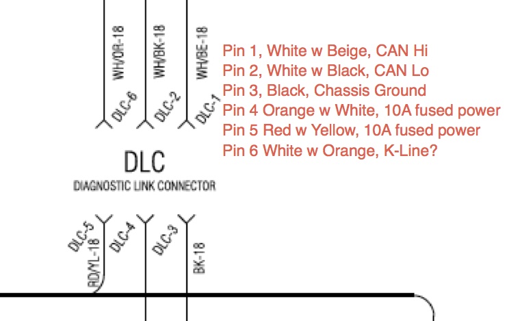
I’m familiar with CAN from my work on the NASA COLBERT treadmill (it used CAN for the motor controller board we sourced from Woodway). The helpful posters on the spyderlovers forum enlightened me on the function and purpose of the K-Line. It apparently is an alternate physical layer to the CAN. I’m betting all the traffic I am interested in is on the CAN line because of its higher bandwidth and multi-drop nature.
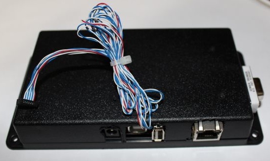
USB to CAN adapters are fairly expensive. The Kvaser I used at Wyle for the treadmill project was outstanding but it was around $700. The Kvaser CAN King software was fantastic too but the cost of entry was just too steep for a project being funded out of my own pocket. I instead opted for this:
The Android Open Accessory Application (AOAA) Kit was a logical choice since I already have familiarity with the NXP microcontroller family and their tools. My experience with Embedded Artists products showed them to be well made and well documented. I ordered the connectors from Deutsch Connectors. Those connectors are expensive but they are quite rugged and well made.
I was hoping that at least some of the CAN traffic was OBD-II compliant so once I got the connectors I built a cable that connected the Spyder diagnostic cable to my OBDPros bluetooth adapter that uses an ELM327 compatible chipset to extract OBD-II data. I used the Torque software on my Android phone to scan the bus but it recognized no flavor of OBDII protocol it understood.
So the next step is to bring the AOA online. I had a little bit of a learning curve bringing it up, turns out it really needs a full 1A power supply. I thought I could get by with an 850mA supply but it threw all kinds of weird errors while writing to flash. I separated the two microcontrollers on the AOA board and populated the D-sub 9 headers (could not find any RJ-45 connectors without integrated magnetics in the lab). Just FYI, the D-sub 9 interface expects a female to female pass through connector – do not use a null modem cable. In my case I used a standard D-Sub 9 extension with a double female adapter.
Once I had the example CAN code compiling, executing, and exchanging messages with their demo code, it was time to build an enclosure. Don’t laugh, I’m a software engineer. Sparx builds a lot cooler enclosures for our projects but I cannot leverage those resources for personal boondoggles (yet).
So this is how far I got before last minute travel pulled me away. At least the airplane trip gave me reading time. It appears the demo web server code for this kit uses an open source FAT FS library for the document root. So next I’ll try to merge the CAN communication example with the Web server / FAT file system and see if I can log the CAN data to disk them serve it up over the network.
For a continuation of this post, click through to see Part 2.


4 Responses
keep up the research I hate having to bring in my spyder to the dealer to tell me what is wrong.
I spent some time messing with it tonight, progress is slow but look for an update soon. Thanks for the feedback.
Can you advise if there was any progress made? It would be great to be able to control or spoof the sensor signals to “desensitize” the overall VSS effect.
Well RATS!!! Per a frustration level perhaps only Charlie Brown could comprehend… I was really hoping for further adventures in conquering the malevolent Can Am Can Bus and render all us technically savvy owners the ability to render the Spiders potential wallet emptying caprices and stomach churning mercurial decision to strand one at usually the least desirable moment violating all owner–vehicle tenants & rules mere not fond memory…
erratic