 SolidWorks and PTC Creo are two of the most popular 3D modeling platforms on the market. Fortunately, I have had the opportunity to use both of these. I used a combination of ProE Wildfire 3, Wildfire 5, and Creo 2.0 for about 3 years, and have been using SolidWorks for almost a month. When comparing Creo and SolidWorks, SolidWorks is generally thought of as being a much simpler and more intuitive tool, and Creo much more powerful and complicated to learn. Before I get into my experiences with learning SolidWorks, I would like to state that in my opinion, an understanding of 3D modeling will yield very successful results with either software.
In the next few sections, I am going to describe my impressions while learning SolidWorks. Since I have only been using SolidWorks for about a month, I fully expect some of my preferences to change as time goes on. I will start with general impressions, move into the sketching tool, and then finish with assemblies. In future posts, I will look more into drawings, and surfacing.
Learning Tools
When I first started learning Wildfire 3, I was an intern at a small development company. The lead engineer gave me a tutorial book and said he would see me in a week. Beyond that tutorial book, and advice of engineers, help was limited. SolidWorks on the other hand has ample tutorials. Many of the tutorials are logically organized, and explained everything very well. Additionally, each feature in SolidWorks seems to have an online entry explaining the details, where many of the intricate details of Creo need to be learned through trial and error.
General Usage
One thing that took quite a bit of getting used to with SolidWorks is not being able to use the Middle Mouse Button to acknowledge prompts. This is something that while using Creo becomes second nature for confirming sketch planes, finishing line chains, and confirming extrudes. The closest equivalent I was able to find in SolidWorks is the double click. In SolidWorks a double mouse click will complete a line chain and exit a sketch.
Another assumption regarding SolidWorks is that it is much more intuitive than Creo. While learning SolidWorks this did seem to be the case with me. Learning SolidWorks has been significantly easier than learning ProE Wildfire 3. Part of this may be the fact that I am comfortable in a 3D modeling environment which helps in learning SolidWorks.
The Sketching Tool
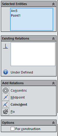
The first difference I noticed was the sketcher setup. With Creo, I enjoy being able to manage all sketch references from a single dialogue box. This allows me to easily manage all of my sketch references. For instance, I can replace reference surfaces and all constraints regarding that specific reference are updated. In SolidWorks, each constraint has to be individually deleted and reestablished. One benefit with the SolidWorks sketching tool is the simplicity of adding geometric constraints. In the sketching tool selecting multiple entities will auto-populate the “Add Relations” menu providing geometric constraints to fit the specific situation. The image below from SolidWorks shows the selected geometry, the existing relations they share, and what new relations can be added.
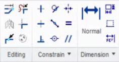
Creo requires the use of the “Constrain” menu to add geometric constraints. You are required to select a specific constraint from the menu (shown below) and then select the geometry to apply it. Once you are familiar with the flow it is not a problem, but it can be a bit cumbersome.
One thing I like better about the Creo Sketcher is that it pushes sketches to be fully constrained. In Creo, the sketcher automatically fills in dimensions. This provides a visual representation of what dimensions need to be added to fully constrain the sketch. As the user modifies or adds dimensions, the color of the dimensions changes from light blue to a darker blue. This can be seen in the image below.
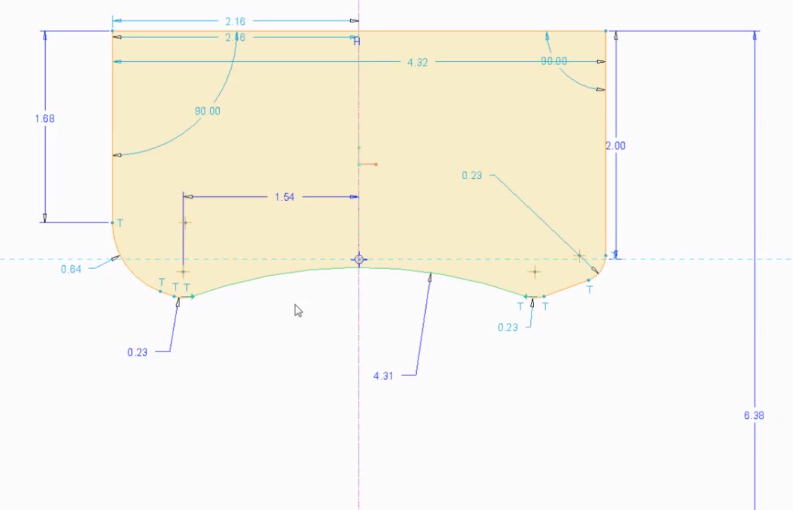
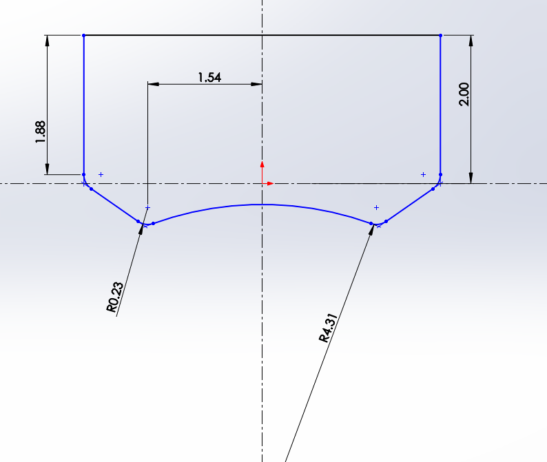
SolidWorks on the other hand, shows fully defined geometry as black and under defined geometry as blue without an indication of what is needed to fully define the sketch. Below is a sketch very similar to the one done in Creo. Both of the sketches have the same number of user defined dimensions. The SolidWorks sketch gives less information regarding what needs to be done in order to define the sketch.
Assemblies
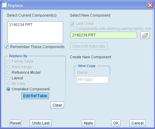
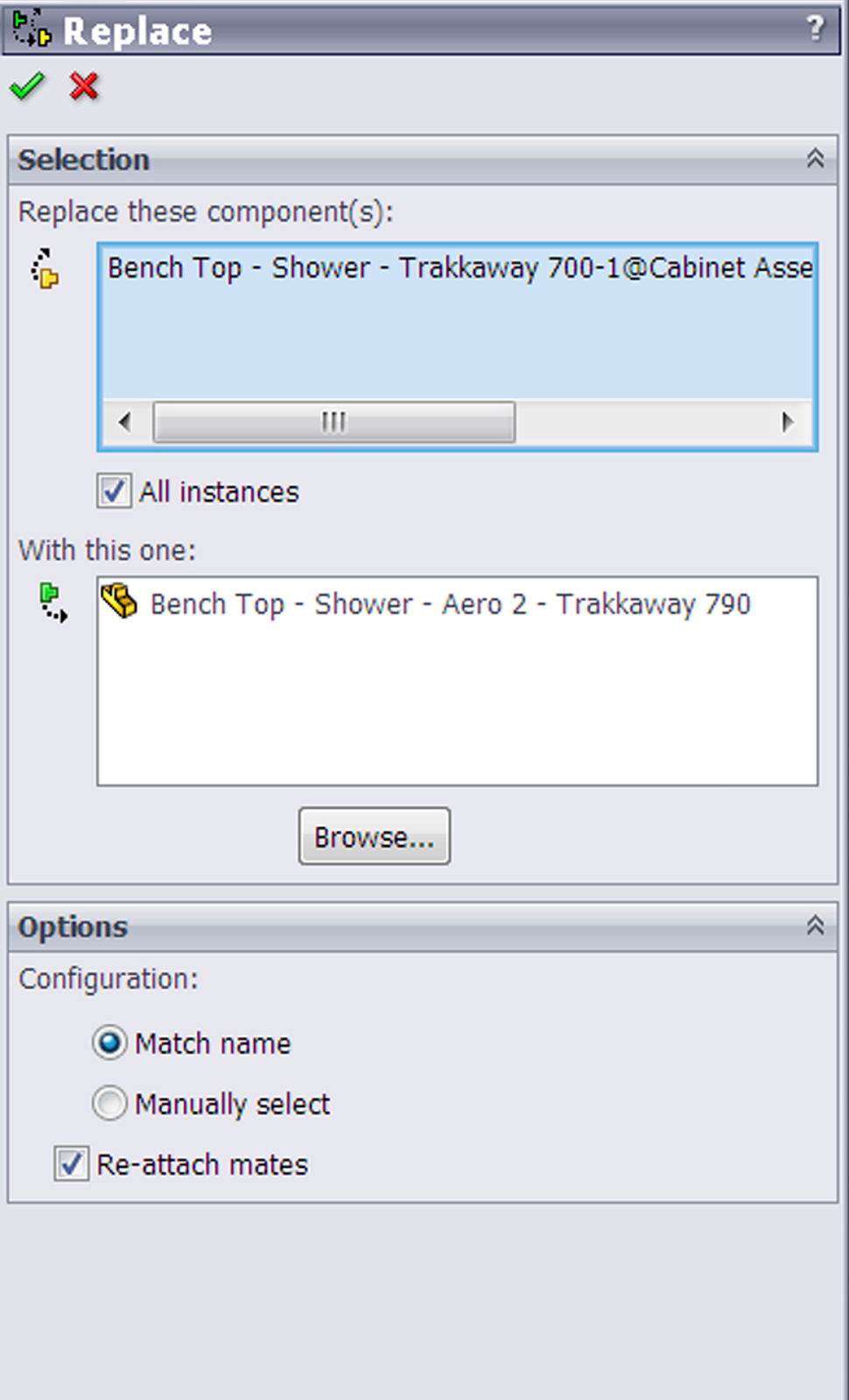
When adding components to an assembly in Creo, the mate dialogue box is automatically opened. Similar to Creo’s sketching tool, assemblies in Creo push to make everything fully constrained. When adding a component in SolidWorks, the mating dialogue needs to be manually started. This is not a big deal, but it is an additional click I need to get into the habit of making. Replacing components within an assembly is much more flexible with Creo. Below are the replace dialogue boxes for both Creo and SolidWorks. As shown in the Creo replace dialogue box, there are a variety of useful options for replacing a component. The replace by unrelated component option in the Creo dialogue box is equivalent to the entire SolidWorks replace tool. The additional options provide for simpler workflow when working with assemblies.
As mentioned I have only been using SolidWorks for about a month. As I gain more experience with SolidWorks and become more comfortable with its features I will continue to compare it to Creo.
One Response
The person who reviewed this is out of date or hasn’t used solidworks. SW is clearly the better. Also dimensions are not the only things to constrain a sketch. There are relations and Solidworks does a better job to inform you if the sketch is fully defined by literally telling you that and changing colour. CREO sketch can change colour once all dimensions are given but not necessarily fully defined with relations.