Basic Appliance Operation
A typical residence has a few staple large appliances such as ovens, dryers, washers, and heat pumps. What powers these modern marvels of convenience and comfort?
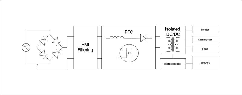
Let us consider the Heating Ventilation and Cooling (HVAC) system, which takes power from the AC mains, converts that to DC, then converts that DC voltage to different supply rails for powering the fan motors, compressor, heating coils, microcontroller, and other supporting digital circuitry. To improve efficiency, a PFC (Power Factor Correction) circuit is likely to be included so that the AC load current and Voltage are in sync. A microcontroller or set of microcontrollers act as the brains for directing how the compressor, fans, and heating coils operate and will monitor feedback on whether corrective actions need to be taken.
Naturally, as there are many different modules and numerous circuit blocks, there are many places where errors might emerge and an exhaustive overview would take more than this preliminary blog post. However, here we will post a few gems from our latest foray into the space.
Setting Yourself Up for Success: Designing for Debug
For board bring up and debug, you want to set yourself up for success with several convenient hooks in place to ensure you can monitor with ease what you need to quickly diagnose various problems.
One of these hooks would include test points with loops or pillars that make it easy for your scope probes to clip onto. Due to layout density, you might consider just using little exposed copper pads. However, unless you have a bed of nails that allow you to actuate probing on command, these little pads will likely cause headaches. Depending on their placement, you will need to spend several minutes disassembling your unit, adding wires, and reassembling your unit. Subsequently if you place several wires on your board, more than what you are probing at a time, your system might become more susceptible to noise as those unloaded wires will be acting as antennas.
Where the test points are placed is also quite important. Naturally, you want to have test points on the inputs, outputs, and alert pins of your circuit blocks. Adding system ground test points as well as test points relative to key IC grounds will make debugging easier especially if you can tether a few scope probe hooks to any given test point potential. While having test points for the aforementioned nodes might be obvious, what may be less apparent is where those test points should go when laying out the board. Experience from hindsight or partnering closely with the mechanical team helps you recognize the need to place these points such that they are accessible with minimal time spent on assembly.
Another point to consider for expediting debug is your connectors. It’s possible that to cram everything you need in one area of your enclosure might not be feasible on a single board. Thus, you might consider connecting another board perpendicular or parallel to your main board. In this scenario, prior to the large-scale fabrication of your boards, you may want to consider a smaller prototype debug batch where you use male and female connectors rather than a single connector that bridges both boards together. This allows you to quickly disconnect your boards, isolate modules, and do simple solder rework that would otherwise not be possible.
One last facet to explore before pivoting to manufacturing and board bring up is test fixtures and simulators. If only reality matched our optimistic projections, it might be a waste. However, as reality can be brutally honest, its nice to have the capability of isolating various modules, boards, or circuit blocks so that you can more quickly distinguish subcircuit issues from system issues. In one of the systems we worked on there was a central board for the power delivery that interfaced with the fan motor drivers board, compressor, heater, and microcontroller logic circuitry board. In several instances it would have been nice to have a testbench for this central board along with dummy loads.
Essential Debug Tools for High-Power Systems
After the board fabrication, you now need to figure out how to troubleshoot the issues despite the layout you have been dealt. Some useful tools include a programmable AC power source, a 4-channel scope, isolated differential probes, current probes, near-field probes, and an isolation adapter for your debugger.
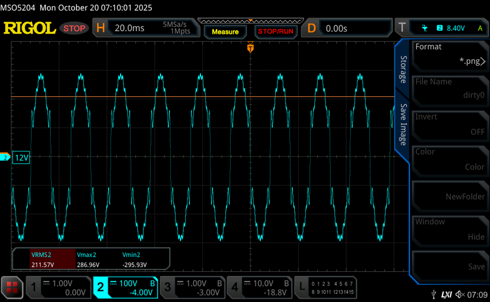
For large power hungry appliances in the United States, the nominal input is expected to be 208 VAC yet these units are often designed to accommodate a ±10% tolerance ranging from 187VAC to 230VAC. To further complicate things, the AC source may not be clean and may introduce various harmonics and transients into the system unrelated to the fundamental. These harmonics might be from local industrial activity, smart meters, utility switching operations, and lightning strikes. A programmable AC supply is useful for determining how robust the system is and whether it will survive various corner cases. Ideally your AC supply should allow you to modify the amplitude of your fundamental AC power, modify the frequency of the fundamental, and give you the ability to inject other harmonics. In our latest project, our client had random spontaneous dropouts in their system that tended to occur in certain test rooms at certain times of the day and were otherwise difficult to duplicate. By using a Chroma 61504 with the aforementioned features we were able to construct a dirty supply signal that reproduced failure rather consistently in under two minutes, which naturally allows more rapid feedback for root cause analysis. Below is an example of what we were able to supply our system under test to more rapidly reproduce failures.
The bedrock of most electronic debug rests on an oscilloscope. As there are likely several modules dependent upon each other, more measurement channels can potentially make life easier. If you have two scopes, you can connect the external trigger output of the first scope to the external trigger input of the second, so that when one scope triggers it issues a trigger to another scope allowing you to grab more data for a single failure event. Another nice feature to have would be an SCPI interface, enabling a PC to control the scope. This makes it possible to set up a test bench sequence that allows you to collect multiple screen captures of rare failure events that happen over long stretches of time.
While scopes empower you to see what is going on with your circuit, you still might need a few accessories to unlock that ability. For systems involving line Voltage and high voltage DC , isolated differential probes are one of the most important accessories. For a typical scope, all channels share the same ground. This poses an issue as you may need to probe small signals that are offset far above the safety earth ground. Attaching a probe ground to one of these signals can quickly fry your probes or scope. So, the isolated differential probes give you the ability to safely gather floating measurements without having to keep track of ground, resort to not grounding a probe, and using math functions to remove offset. The isolated differential probes also reduce loading and remove common-mode noise. We use Picotech TA041 probes to quickly probe around the system ranging from the AC main’s input, a floating DC-DC converter used for the PFC, signals related to a flyback converter, and various logic from the microcontroller.
Another oscilloscope accessory to consider is the current probe. Current probes can provide key high-level insights into system operation. If you see a surge in current, that can indicate state changes, fault events, as well as possible sources of EMI. In the figure below, the yellow trace corresponds to the input current. Here we see a large transient ripple at power on, which generated EMI events that periodically caused issues for one of the microcontrollers.
Verifying Power Integrity and Protection Behavior
After confirming initial power-up behavior, intermittent faults may appear after minutes or hours.
After debugging the initial power on sequence and whether the system is exhibiting the general expected behavior. There are the more insidious head scratching errors that mysteriously occur after minutes to hours of operation. Unless your microcontroller issued some tangible warning, it’s time to pull out the probes and put on your thinking cap.
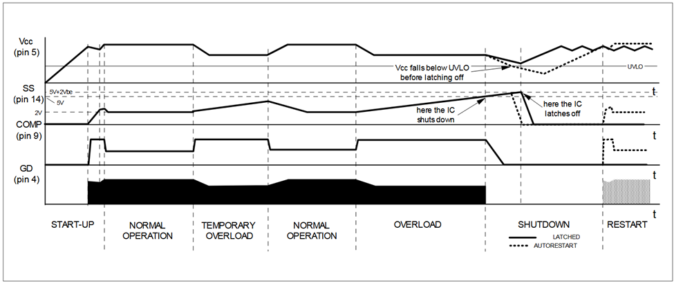
Good places to start include looking at the power rails and microcontroller. For power, it makes sense to look at alert and enable pins. Power chips can have all types of protection including overvoltage, undervoltage, short circuit, and overtemperature. Some datasheets may be nice enough to give you some diagrams of how the device responds to rogue behavior. Such an example can be seen in this diagram.
Due to all the features many switch mode power supplies have these days, its possible that a given device might have multiple different configurations that unlock different modes of operation such as feedforward, frequency foldback, etc. When odd failures are happening it may make sense to review the schematic and verify all the parts required of a particular operating mode are properly populated. For the switch mode power chip we last reviewed, there was a pull-down resistor that indicated feedforward operation was desired, yet the corresponding filter that is needed for that operation was not populated. After placing that filter, the mysterious fault that occasionally brought the system down went away.
Leveraging Automation for Intermittent Failures
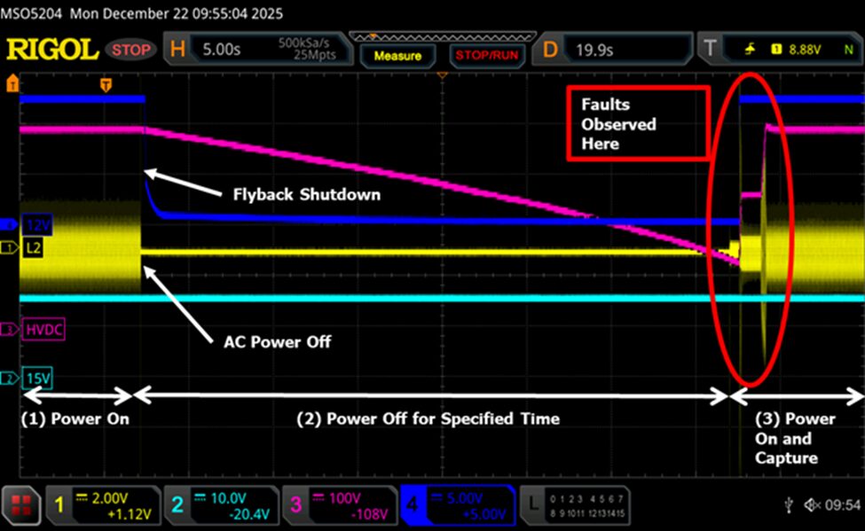
At some point in your debugging, you may realize that a very specific series of events need to occur to crash your system and even then it does not happen every single time. One of our clients had an issue where a specific off duration spanning tens of seconds during multiple power cycles would exhibit the microcontroller getting stuck and ultimately the system crashing. As the failure rate was about 3% of the power cycles, you can imagine that hours of attempts had to pass before accumulating enough faults to start formulating a meaningful hypothesis and possible corrective actions. As such, you could deduce that the unfortunate engineer attempting to do these tests manually might burn-out and get gradually sloppier with each cycle. Consequently, we put together a python script to automate the task. Subsequently, that script churned through thousands of power cycles through the day and into the night and ultimately delivered a payload of useful debug information to process after we enjoyed our morning coffee the following day. The illustration below illustrates the kind cyclical conditions we were able to generate and test with our automation script:

Conclusion: Debugging Complex Power Systems with Confidence
Large systems are comprised of several modules working in harmony to provide the climate control amenities we all appreciate. These modules and their respective subcircuits provide numerous points where faults can lurk. At Sparx Engineering, we combine hardware expertise, diagnostic tooling, and automated testing strategies to isolate intermittent failures and provide actionable corrective solutions.
If your team is facing power system instability, EMI issues, or intermittent controller faults, structured debug methodology makes all the difference.