Understanding 3D Modeling File Types: A Guide for SolidWorks Users
In the world of 3D CAD modeling, every software has its own native file type and varying degrees of support for interchangeable file formats. This makes managing files across different platforms and programs a challenge—especially when you’re unsure which files are editable, viewable, or even importable.
In this guide, we’ll explore the most common 3D modeling file types, their roles in SolidWorks, and which formats offer full editing capability, limited functionality, or no compatibility at all.
Popular CAD Programs
There are a variety of programs available for 3D modeling, each with its own file structure. Depending on the program used, the file structure will look a little different from another program. Some of the commonly used programs are:
At Sparx Engineering, our standard CAD platform is SolidWorks, and this guide is written with SolidWorks users in mind.
Core 3D CAD File Categories
Engineers typically work with three main file types across all CAD programs:
-
Parts – Single components (e.g., bolts, brackets, housings)
-
Assemblies – Collections of parts constrained together
-
Drawings – 2D documentation for manufacturing or assembly
Let’s break these down by file type and compatibility.
Parts
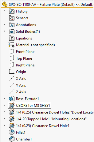
A part file is a singular component. A part file is where the highest detail of a design is done. A part is built up by creating different features, which control the thickness, hole patterns, shape, etc. of the given part. A part is composed of a feature tree, which is the list of all the features used to design that part. These are singular components such as a bolt, bracket, beam, cover, etc.
Native
- SLDPRT
The file type for a single part component is referred to as the file extension (.SLDPRT) in SolidWorks. These are parts made and saved in the SolidWorks CAD program, and allow the most detailed editing when used in SolidWorks. This means that when imported into SolidWorks, it allows for the entire feature tree to be seen and edited.
Generic 3D Geometry
- STEP
- IGES / IGS
A generic, or general 3D geometry files give access to the part and what is looks like, but does not allow editing of the feature tree used to create that part. Although the feature tree is not accessible, new features can still be added to change the design of the part. Generic 3D geometry files are typically used to exchange part files when two companies may have not used the same 3D CAD modeling program.
Generic 3D Mesh
- STL
- OBJ
- WRL
A 3D mesh file uses lines and data points to create surfaces that represent the part. While geometry is viewable, the files are often large – even for small components – and difficult to work with. The feature tree is not accessible and accuracy of features is not easily measured. Generic 3D mesh models are most commonly used for 3D printing.
Alternate Native Files – Importable
- Inventor – IPT
- Cadkey – PRT
- Catia Graphics – CGR
- Creo – PRT / XPR
The other CAD programs also use their own native files which Solidworks is able to import, listed above. These files will have limited access to feature history and tree, but are able to be viewed and edited with new features.
Alternate Native Files – Non-Importable
- Catia – CATPART
There are also file types that Solidworks is unable to import and work with, which are listed above. While a different program may be able to use these files, Solidworks cannot.
Part Example

Assemblies
An assembly is a document that is comprised of multiple parts. The parts are arranged using constraints which help define where parts start and stop. In more advanced assemblies constraints can sometimes allow parts to move as they might when assembled in the real world. Assemblies are used to model multi-body components as well as a collection of parts that have movement involved. Some examples of an assembly would be a gearbox, power tool, and enclosure with electronic components.
Native
- SLDASM
These are assemblies made and saved in the Solidworks CAD program, and allow the most detailed editing when used in Solidworks. When imported into Solidworks, it allows the constraints to be edited. The constraints are able to be added, deleted, and have the details changed as necessary. We are also able to see each part and add / remove parts as necessary. For an assembly to be imported properly, all of the part files within the assembly will be required as well.
Generic 3D Geometry
- STEP
- IGES / IGS
A generic 3D geometry files gives access to the assembly and the general arrangement of components, but does not allow editing of the specific parts or constraints that were originally used.
Generic 3D Mesh
- STL
- OBJ
- WRL
A 3D mesh file uses lines and data points to create surfaces that represent the parts. While geometry is viewable, the files are often large – even for small assemblies – and difficult to work with. These file extensions are often not usable within SolidWorks for assemblies.
Alternate Native Files – Importable
- Inventor – IAM
- Cadkey – CKD
- Catia Graphics – CGR
- Creo – ASM / XAS
The other CAD programs also use their own native files which SolidWorks is able to import, listed above. These files may have limited access to the constraints or ability to edit but are able to be viewed.
Alternate Native Files – Non-Importable
- Catia – CATPRODUCT
There are also file types that SolidWorks is unable to import and work with, which are listed above. While a different program may be able to use these files, SolidWorks cannot.
Assembly Example

Drawings
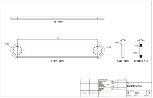
Drawings are 2D representations of given parts or assemblies. They are used to give manufacturing directions, dimensions, tolerancing, assembly instructions, and information about the product without needing the CAD file. A drawing is created based on the part or assembly and is used as supplemental information to the 3D data. Drawings are also used to help control revision history of parts and assemblies. If an existing product is changed, the drawing will help document said changes and allow necessary parties to see the updates.
- Part drawings are often used for fabrication of individual parts and provide enough information for the overall geometry and dimensions. It often also includes tolerances, which govern how accurate the dimensions need to be for the part.
- Assembly drawings are used to give part lists, general assembly details, and needed information of how the assembly fits together. Sometimes dimensions are present but are not always required.
Native
- SLDDRW
This file type is a drawing created in SolidWorks and requires the given SolidWorks part to be correctly opened. For part drawings, the SolidWorks part is required to open properly. If the drawing is for an assembly, the assembly file along with all of the part files are required to open properly.
If both the part and drawing are provided, we are able to completely adjust all aspects of the drawing. We can add / remove dimensions, tables, change drawing views, and adjust the drawing to the required format.
Generic 2D Geometry
- DWG
- DXF
The DWG and DXF files are able to be imported into SolidWorks and allow us to view the drawing and its information. The part files are not required, and the files can be opened by themselves.
We are able to make minor adjustments to the drawings, but are limited in adding tables, changing view angles, and editing the format due to the generic aspect of the file.
Alternate Native Files – Non-Importable
- Adobe – PDF
PDFs are able to be viewed outside of SolidWorks, but unable to be used in SolidWorks. If changes are desired, and only PDFs are available, we often recreate the drawing in SolidWorks based on the provided PDF to achieve the necessary changes.
Drawing Example
Summary Table: Best File Types for SolidWorks
| File Type | Format | Editable in SolidWorks | Notes |
|---|---|---|---|
| Part | .SLDPRT |
✅ Full access to feature tree | Native |
| Assembly | .SLDASM |
✅ Full access to constraints | Native |
| Drawing | .SLDDRW |
✅ Requires linked part/assembly | Native |
| Geometry Exchange | .STEP, .IGES |
✅ Geometry only (no history) | Good for cross-platform use |
| Mesh Files | .STL, .OBJ |
❌ View-only or 3D print | Not suitable for editing |
| 2D Drawings | .DXF, .DWG |
⚠️ Limited edits | No parametric features |
.PDF |
❌ | Recreate if edits are needed |
Conclusion
In review, the best possible file types to work with is the native file type for each CAD program. While multiple types are usable, the native file type offers up the best ability to make any desired changes.
For SolidWorks specifically, the best file types to import are SLDPRT (part), SLDASM (assembly), and SLDDRW (drawing). If these are unavailable, the next best options are STEP for parts and assemblies, and DXF for drawings.
Need Help Choosing the Right File Format?
If you’re unsure what file types you have or which ones are best for your project, Sparx Engineering can help. Our team works across industries and software platforms to convert, clean up, and deliver production-ready CAD files.
- ✅ Visit our Mechanical Engineering page to learn more
- 📩 Contact us here to get started with your 3D modeling project.